
This section contains architectural and construction detailing for integrating ProREZ flooring systems into a variety of structural and substrate conditions. These documents include precise technical diagrams for floor-to-wall transitions, isolation joints, floor drains, fiberglass mesh coves, and transitions to other flooring materials. Each drawing is tailored to ensure proper installation practices that meet performance and durability standards in industrial and commercial environments.
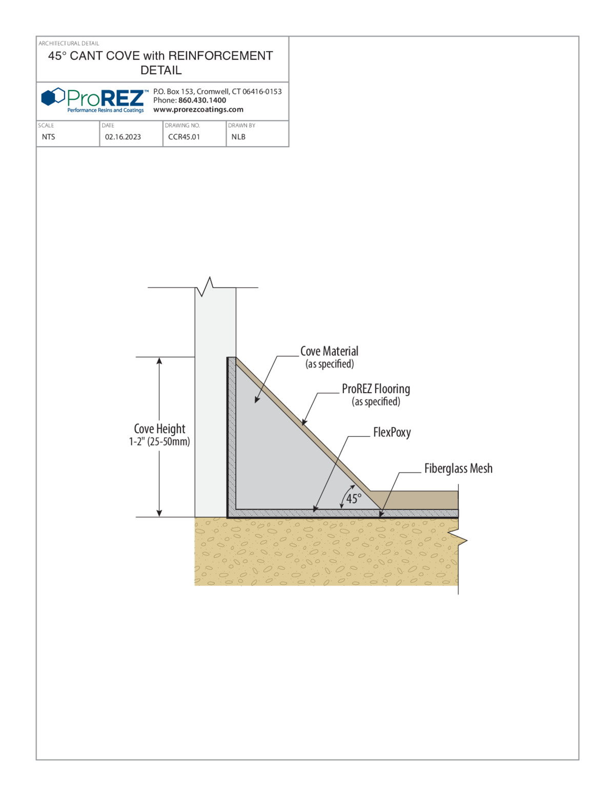
45° Cant Cove with Reinforcement Detail
This detail illustrates a 45° cant cove where the floor meets the wall, with embedded reinforcement mesh for added strength. It specifies the angle of the cant and the location of the reinforcement, along with dimension callouts for height and width. The drawing highlights the layering sequence, showing substrate prep, base coat, reinforcement placement, and topcoat. A full title block includes the drawing number, scale (NTS), date, and contact information for ProREZ Flooring. Installers can use this as a guide to form a durable, reinforced cove that resists cracking and provides a smooth transition between floor and wall.
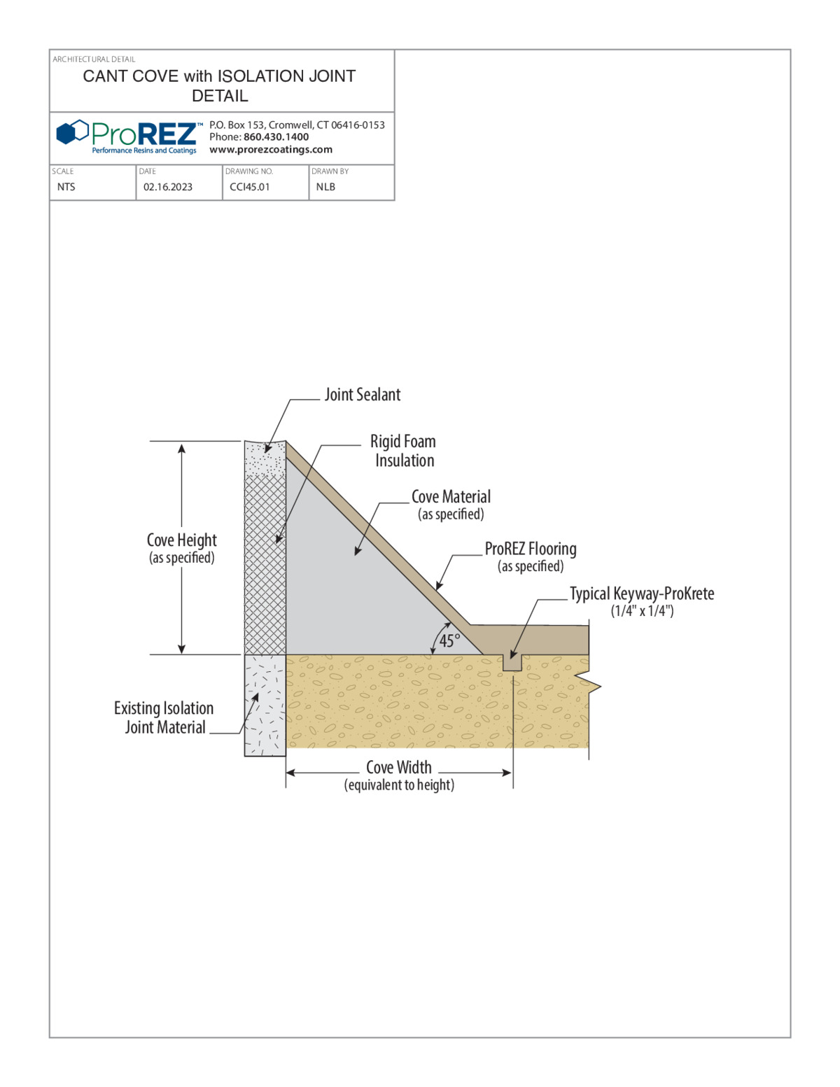
View PDFCant Cove with Isolation Joint Detail
This detail depicts a cant cove formed up the wall where the floor meets an isolation joint. It specifies the geometry of the cove (typically a 3″ radius or as noted) and shows the location of the isolation joint strip and sealant. The drawing calls out substrate preparation, primer coat, and base coat materials, followed by the cant cove application. A reinforcement layer is shown at the cove base to prevent shrinkage cracking. Title block data (drawing number, scale NTS, date, and ProREZ contact) is included for reference and coordination.
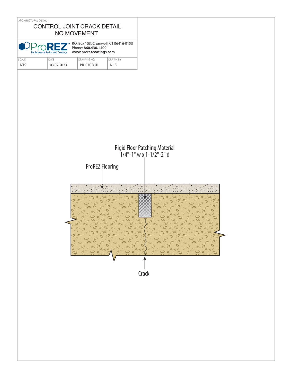
View PDFControl Joint Crack Detail
This detail provides a method for repairing a control joint or crack in a rigid concrete floor using a rigid floor patching material. It indicates typical crack widths (¼″ to 1″) and depths (1½″ to 2″) and shows how to install the patching compound. The drawing includes instructions for blade angle, backer rod placement if needed, and finish profile for a seamless repair. A title block contains drawing number PR-CJCD.01, scale (not to scale), date, and ProREZ Flooring contact information. Installers use this as a guide to fill and seal cracks while maintaining structural integrity of the floor system.
View PDF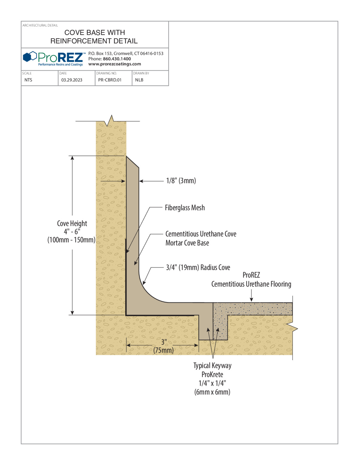
Cove Base with Reinforcement Detail
This detail illustrates how to form a cove base with embedded reinforcement mesh for added durability at the wall-floor junction. It specifies the cove radius (typically 3″) and shows the position of the reinforcement layer within the base coat. The drawing calls out substrate profiling, primer application, and base coat before embedding the mesh. It then shows a finish coat to seal the cove. A title block contains drawing number PR-CBWR.01, scale (not to scale), date, and ProREZ contact details. Contractors use this as a guide to create a reinforced cove base that resists impact and cracking.
View PDF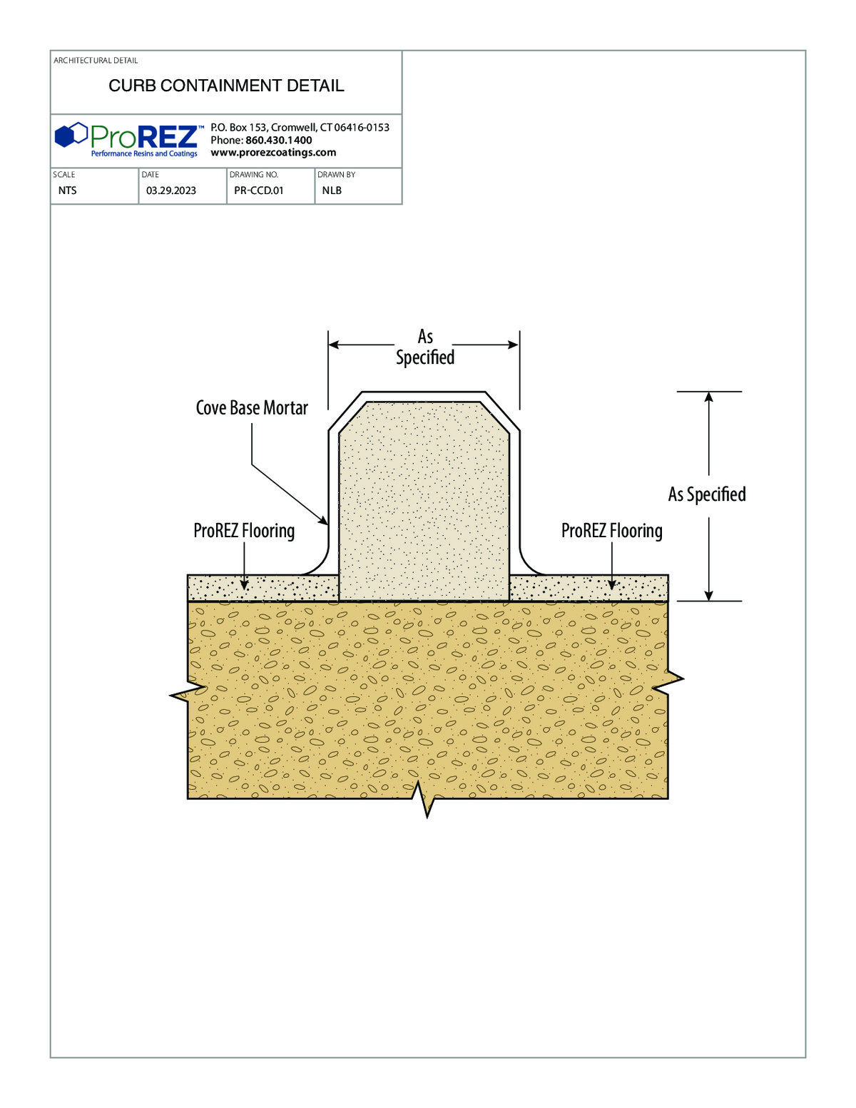
Curb Containment Detail
This detail depicts a curb used for containment areas, such as chemical or washdown zones. It specifies curb height (typically 4″ or 6″), thickness, and taper, along with the location of reinforcement wire mesh within the curb. The drawing calls out substrate preparation, a mortar or base coat, placement of mesh reinforcement, and a final topping coat for a seamless containment barrier. A title block includes drawing number PR-CCD.01, scale (not to scale), date, and ProREZ Flooring contact information. Installers refer to this as a guide to build a robust curb that prevents liquid migration beyond the designated area.
View PDF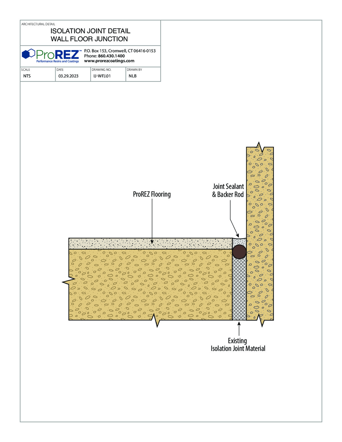
Isolation Joint Wall‑Floor Junction Detail
This detail depicts an isolation joint at the junction of a wall and floor, showing how to terminate a floor coating system in that condition. It specifies placement of the joint strip (typically foam or neoprene) against the wall and the location of backer rod and sealant at the floor level. The drawing calls out substrate profiling, primer coat, and base coat right up to the joint strip. It also shows how the cove base or finish coat terminates at the joint. Title block information includes drawing number PR-IJWF.01, scale (not to scale), date, and ProREZ contact details. Installers use this drawing to maintain a controlled joint that prevents cracking and allows for independent movement of wall and floor.
View PDF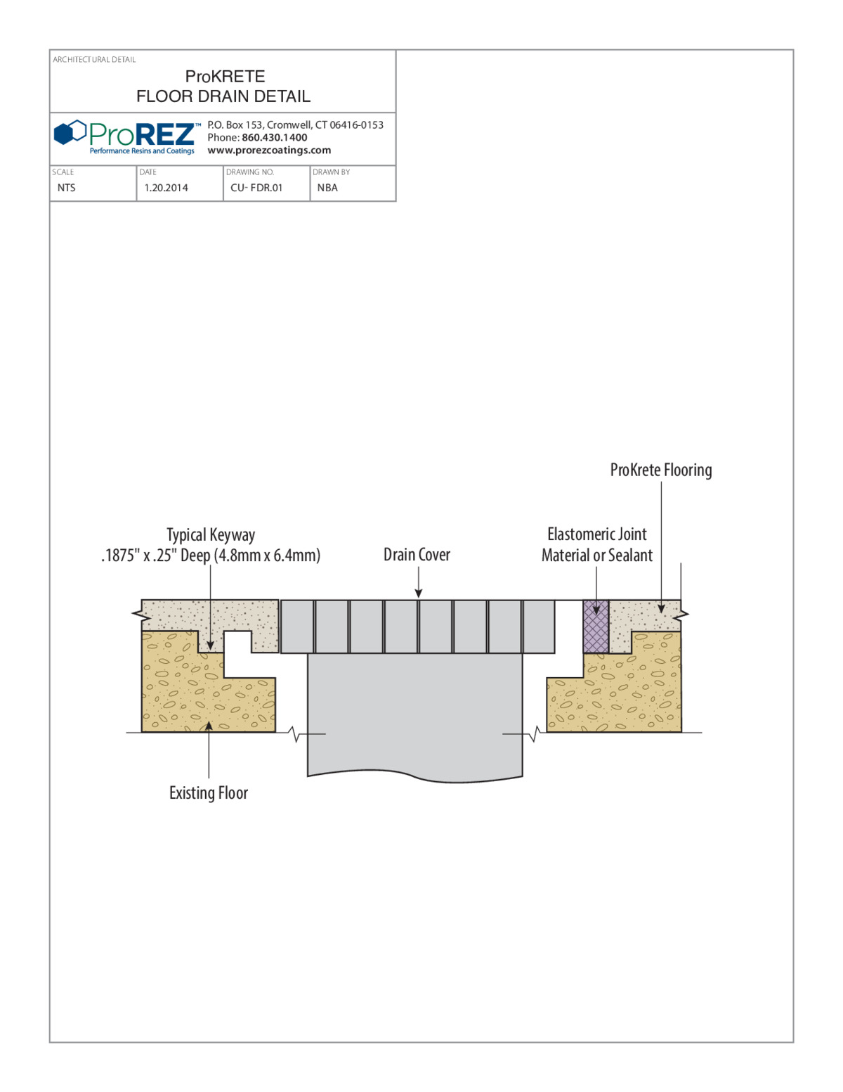
ProKrete CU Floor Drain Detail
This detail illustrates integration of a floor drain within the ProKrete CU cementitious urethane system. It specifies slope requirements (typically 1–2% toward the drain) and shows the waterproof flange detail that ties into the drain body. The drawing calls out substrate profiling, primer coat, and mortar bed build‑up sloped at the correct angle to ensure positive drainage. It also shows how the cove base transitions into the drain curb for a seamless, watertight connection. A title block includes drawing number PR-CUFD.01, scale (not to scale), date, and ProREZ contact information. Installers reference this to properly set drains and slope surrounding floor areas for sanitary, code‑compliant installations.
View PDF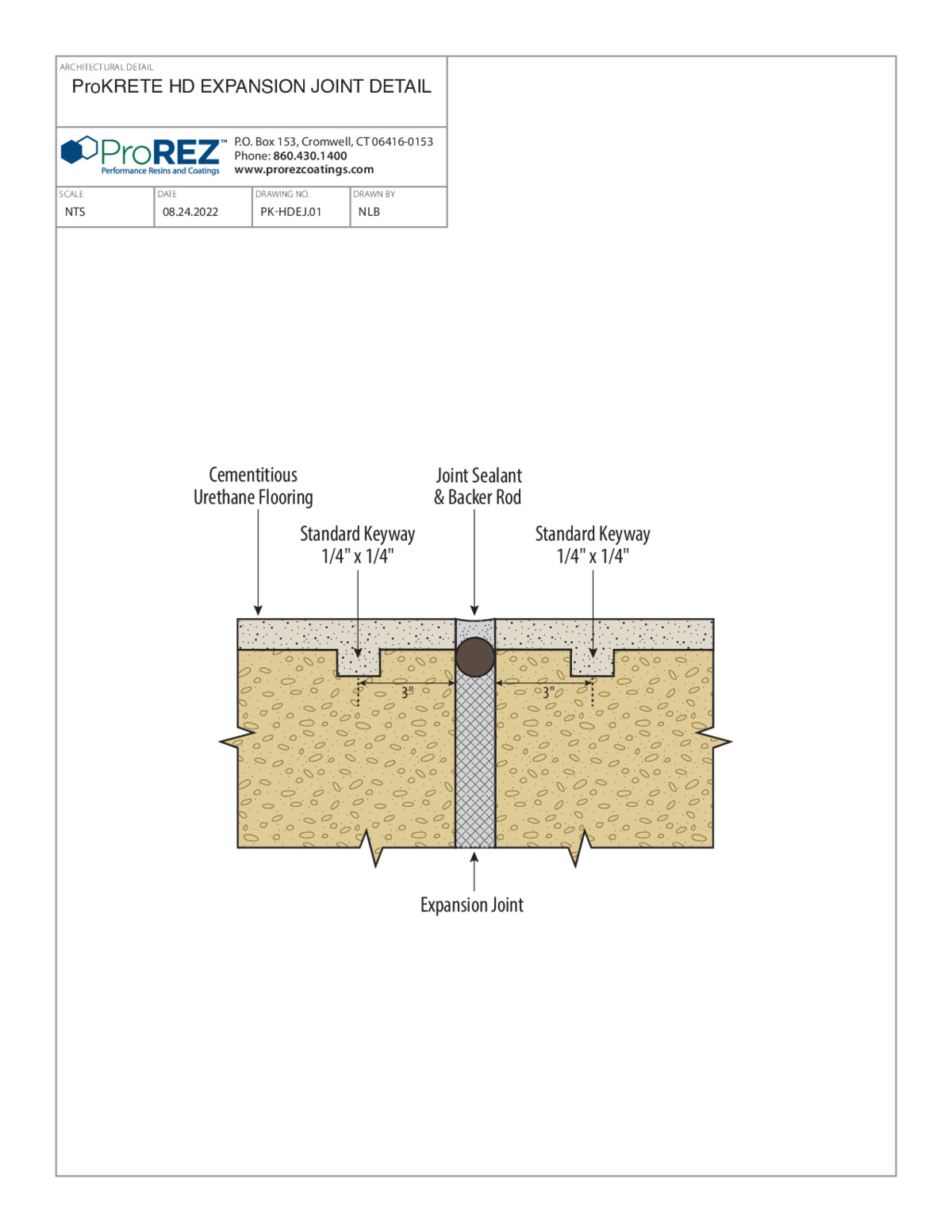
ProKrete HD Expansion Joint Detail
This detail shows how to construct an expansion joint within a ProKrete HD high‑density cementitious urethane system. It specifies the location and dimensions of the joint filler (compressible material) and the compatible sealant to bridge the joint. The drawing calls out substrate profiling, primer application, and the edge treatment of the mortar up to the filler. It also shows how to integrate a cove base that terminates at the joint without impeding movement. A title block contains drawing number PR-EJHD.01, scale (not to scale), date, and ProREZ contact information. Installers reference this to maintain a controlled gap that accommodates thermal or structural movement without compromising the floor system.
View PDF
Tech Center 45° Cant Cove Detail
This detail illustrates a 45° cant cove at the junction of floor and wall in a technology‑center application. It indicates the geometry of the cant (45° angle) and shows placement of reinforcement mesh within the base coat. Substrate profiling, primer coat, and base coat layers are called out before embedding the mesh and applying the finish coat. Dimension callouts specify the height and projection of the cant for a smooth transition. A title block includes drawing number TC-45CCD.01, scale (not to scale), date, and ProREZ contact information. Installers use this to form a precise, reinforced cove that accommodates heavy equipment and frequent cleaning in tech areas.
View PDF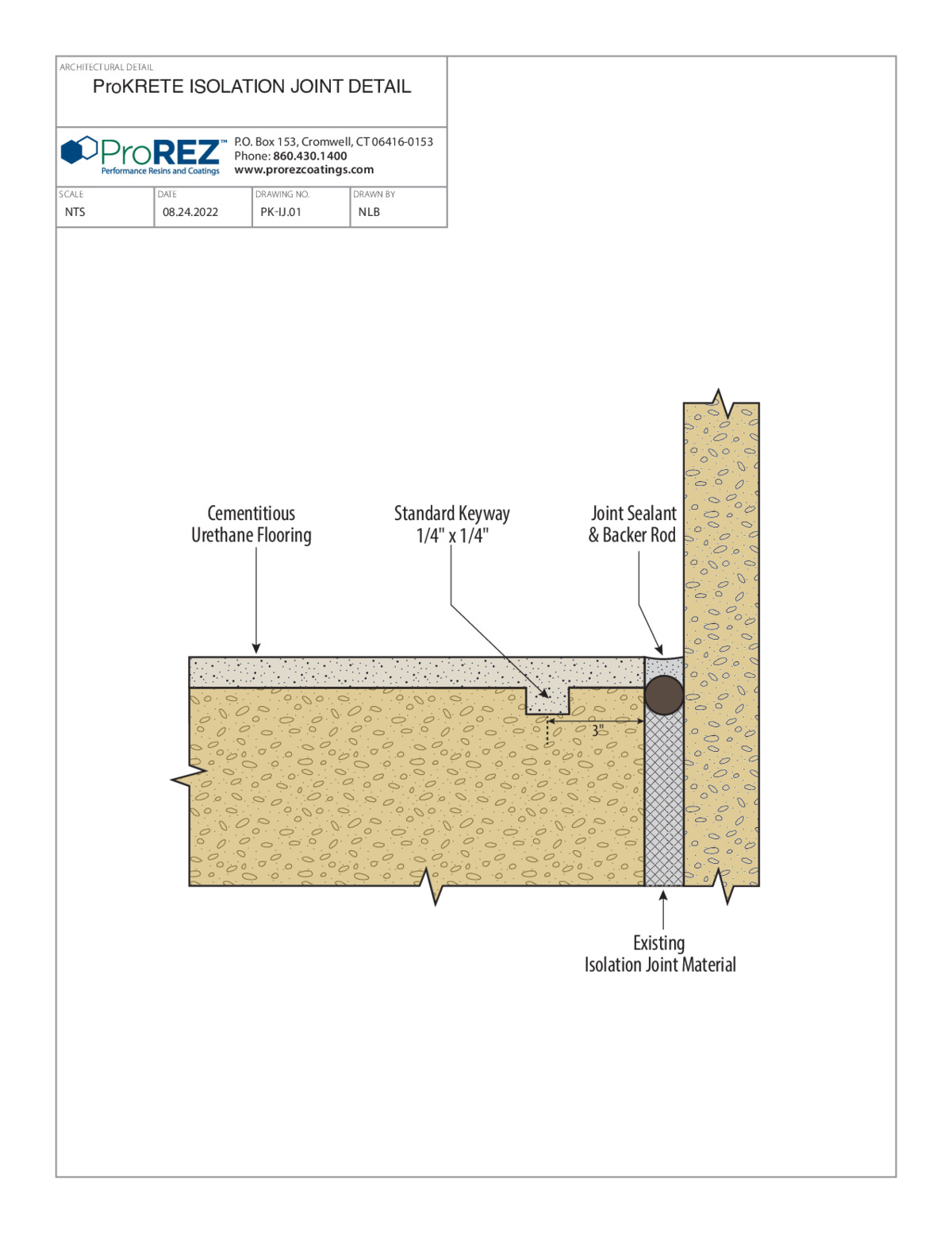
ProKrete Isolation Joint Detail
This detail depicts how to form an isolation joint in a ProKrete flooring system, showing the placement of a compressible joint filler and compatible sealant. It specifies substrate profiling, primer coat, and mortar bed up to the joint filler. The drawing calls out how to maintain a cove base on one side of the joint without crossing it, preserving independent movement. A title block includes drawing number PR-IJPK.01, scale (not to scale), date, and ProREZ contact information. Installers follow this for proper separation between the floor and adjacent structures, preventing cracks due to differential movement.
View PDF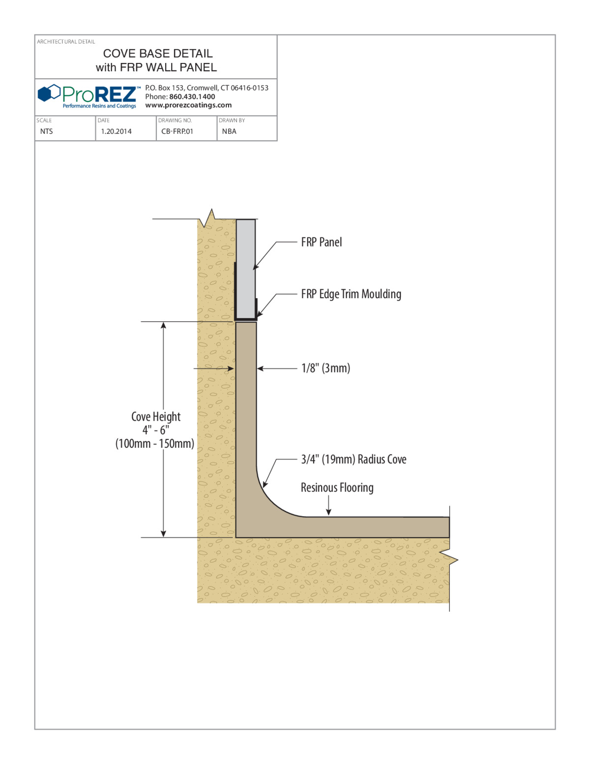
Tech Center Cove Base Detail (Epoxy Floor with FRP Wall Panel)
This detail illustrates a cove base where an epoxy floor system ties into a fiberglass‑reinforced plastic (FRP) wall panel in a technology‑center environment. It specifies a 3″ cove radius, substrate profiling, and primer coat before applying the base coat. The drawing shows embedding reinforcement mesh up to the FRP panel and applying appropriate sealant or adhesive between the epoxy and FRP interface. Finish coat transitions into a termination strip at the FRP panel for a hygienic seal. A title block includes drawing number TC-CBEPF.01, scale (not to scale), date, and ProREZ contact information. Installers follow this to ensure a seamless, watertight junction that resists delamination and meets sanitary requirements.
View PDF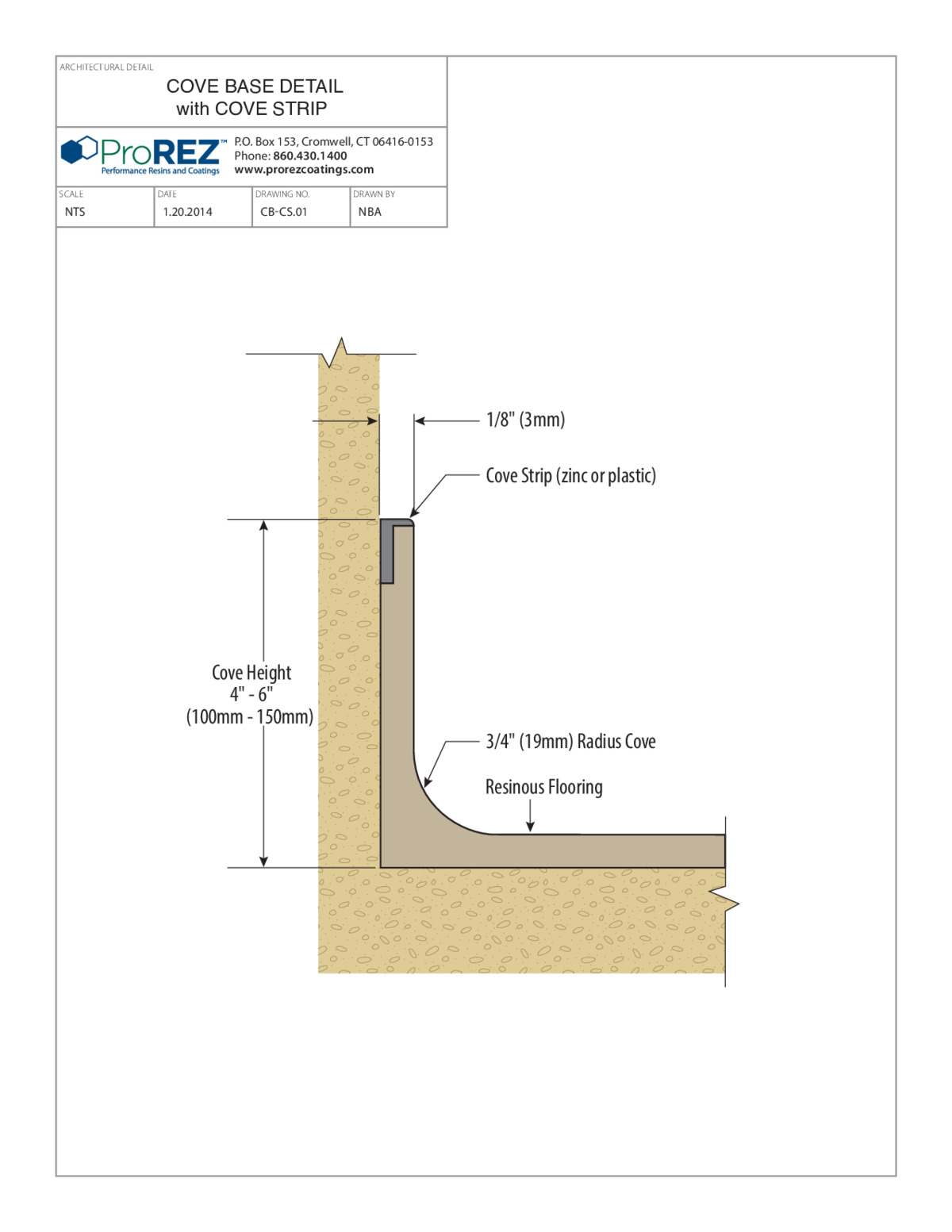
Tech Center Cove Base Detail with Cove Strip
This detail illustrates a cove base assembly in a technology‑center environment, incorporating a prefabricated cove strip for a clean termination. It specifies cove height (3″), base coat, and the location of the cove strip anchored to the substrate. The drawing shows a reinforcement mesh layer positioned above the strip and a finish coat over the top. It calls out pre‑sloping, substrate profiling, primer coat, and final seal coat to achieve a watertight cove. A full title block includes drawing number TC-CBDS.01, scale (not to scale), date, and ProREZ contact. Contractors use this drawing to install a cove base that integrates a durable strip for heavy‑duty cleaning operations.
View PDF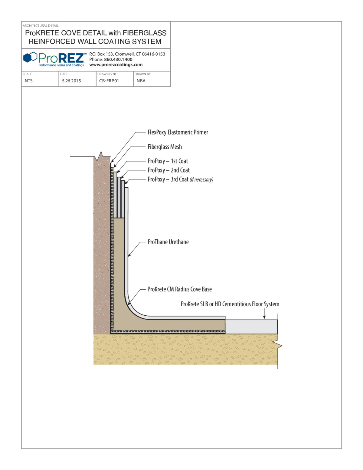
Tech Center Fiberglass Mesh Cove Detail
This detail shows how to construct a cove base in a technology‑center environment using fiberglass mesh for reinforcement. It specifies a standard cove radius (3″) and shows the mesh embedded within the base coat for crack control. Substrate profiling, primer application, and base coat placement are called out, followed by positioning the fiber mesh just below the finish coat. Dimension callouts indicate cove height and projection. A title block displays drawing number TC-FMCBD.01, scale (not to scale), date, and ProREZ contact details. Installers follow this to achieve a reinforced cove base that resists delamination and provides a smooth, hygienic transition between floor and wall.
View PDF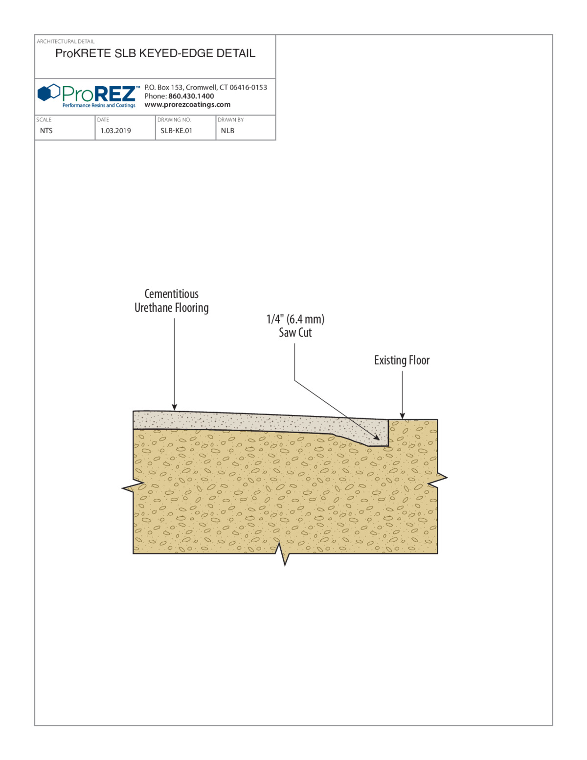
Tech Center ProKrete Keyed Edge Detail
This detail depicts preparing a keyed edge for ProKrete overlay in a technology‑center setting to ensure mechanical bond. It specifies dimensions for a saw‑cut notch (e.g., ½″ deep by ¾″ wide) and shows the placement of underlayment or mortar to fill the notch. The drawing calls out substrate profiling, primer coat, and the mortar bed before troweling the overlay. It also shows a termination seal to prevent moisture ingress. Title block information (drawing number TC-PEKD.01, NTS scale, date, and ProREZ contact) is included for field reference. Installers follow this drawing to create a controlled edge that locks the overlay into place and resists delamination.
View PDFProCryl SF Single Broadcast CSI Specification
This CSI specification provides comprehensive guidelines for ProCryl SF Single Broadcast, including project scope, referenced standards, and submittal requirements. It details material properties such as tensile strength, flexibility, chemical resistance, and application parameters. Substrate preparation requirements—such as surface profile, moisture limits, and priming—are specified along with installation procedures including mixing, application methods, and curing. Quality assurance and testing criteria (e.g., adhesion, hardness, and chemical exposure tests) are also defined to ensure performance compliance. The specification concludes with maintenance recommendations and warranty conditions.
View PDF